
Explosion-Proof (Ex d) vs Intrinsically Safe (Ex i): Which Solenoid Valve Should You Choose?
October 15, 2026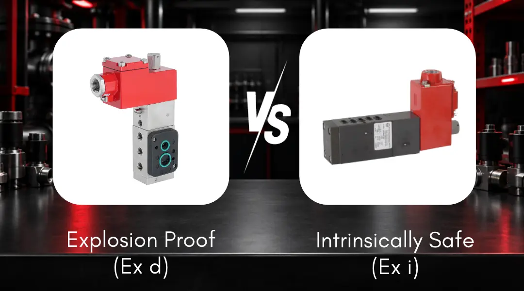
A technical guide for EPCs, OEMs, instrumentation engineers, and end users specifying solenoid valves for classified locations — covering protection principles, certification, loop validation, and selection criteria.
Explosion-proof (Ex d) and intrinsically safe (Ex i) solenoid valves are both engineered for hazardous-area installations, but they protect against ignition in fundamentally different ways. For EPCs, OEMs, instrumentation engineers, and end users specifying solenoid valves for classified locations, understanding this difference is critical to safe, compliant, and reliable system design.
In hazardous areas, the choice between Ex d and Ex i is not simply a product preference. It affects certification compliance, wiring architecture, maintenance practice, safety documentation, spare-part management, and long-term plant reliability.
Ex d — Flameproof / Explosion-Proof
Contains an internal explosion inside a certified enclosure and prevents flame propagation to the surrounding atmosphere.
Typically suitable for:
- High-power actuation, rugged environments
- Upstream oil & gas, refineries, pipelines
- Offshore platforms
- Zone 1 / Division 1 and Zone 2 / Division 2
Ex i — Intrinsically Safe
Limits electrical energy in the circuit so ignition cannot occur, even under defined fault conditions.
Typically suitable for:
- Low-power instrumentation
- Zone 0 areas
- Process control loops
- Safety-critical systems and instrumentation-dense plants
Common certification frameworks include: FM, CSA, UL, ATEX, IECEx, PESO, BIS, and other regional approvals depending on the project location.
Why Standard Solenoid Valves Cannot Be Used in Classified Locations
In industries such as oil & gas, petrochemical refining, pharmaceutical manufacturing, chemical processing, LNG, mining, and hydrogen handling, flammable gases, vapors, or combustible dust may be present continuously, intermittently, or during abnormal conditions.
Standard solenoid valves can become ignition sources because of:
- Electrical sparks during coil switching
- Arcing at terminals or contacts
- High coil surface temperature during continuous energization
- Loose wiring or poor terminations
- Incorrect cable glands or enclosure entries
- Unsuitable insulation or ingress protection
Hazardous-location-certified solenoid valves are designed to reduce or eliminate these ignition risks through approved protection concepts. Two of the most common protection concepts used for solenoid valves are Explosion-Proof / Flameproof Ex d and Intrinsically Safe Ex i.
Hazardous Area Classification: NEC Division vs IEC Zone System
Hazardous areas are classified based on the likelihood and duration of explosive atmosphere presence. US-based projects commonly use the NEC Division system, while international projects usually follow the IEC Zone system. Many export-oriented projects specify both systems simultaneously, especially in LNG, offshore, refinery, chemical, and packaged skid applications.
| IEC Zone | NEC Division Equivalent | Description | Hazard Presence Level |
|---|---|---|---|
| Zone 0 | Division 1 | Explosive gas atmosphere continuously present or present for long periods | Gas is continuously present or present for extended duration |
| Zone 1 | Division 1 | Explosive gas atmosphere likely during normal operation | Gas may regularly enter the flammable range during normal process operation |
| Zone 2 | Division 2 | Explosive gas atmosphere not likely during normal operation; if present, only for short duration | Gas may appear during leaks, abnormal events, or equipment failure |
| Zone 20 | Division 1 Dust | Combustible dust cloud continuously or frequently present | Dust is consistently suspended in air in explosive concentration |
| Zone 21 | Division 1 Dust | Combustible dust likely during normal operation | Dust handling or processing may create explosive dust atmosphere |
| Zone 22 | Division 2 Dust | Combustible dust not likely during normal operation | Dust appears only during abnormal or short-duration conditions |
Engineering Note for EPCs, OEMs, and Instrumentation Teams: Before selecting a hazardous-area solenoid valve, the following documents should be reviewed: Area Classification Drawing, Hazardous Area Schedule, gas group classification, temperature class requirement, process fluid SDS / MSDS, project specification, client-approved vendor list, required certification scheme, installation standard, and instrument index and cause-and-effect chart, where applicable. The valve certification must match the actual hazardous-area classification, not only the general plant location.
Explosion-Proof / Flameproof Solenoid Valves — Ex d
Explosion-proof or flameproof protection is a containment-based strategy. The electrical parts of the solenoid are housed inside a strong certified enclosure. If an ignition occurs inside the enclosure, the enclosure withstands the internal pressure and cools escaping gases through flame paths before they can ignite the surrounding atmosphere.
Key Principle: In Ex d protection, ignition may occur inside the enclosure, but it must not propagate outside.
Key Engineering Characteristics of Ex d Solenoid Valves
- Heavy-duty metallic enclosure
- Certified flame path joints
- Suitable for Zone 1 and Zone 2 applications
- Often suitable for Class I Division 1 and Division 2 locations
- Available for higher-power coils
- Suitable for direct connection to PLC or DCS outputs, depending on project design
- Rugged construction for outdoor, offshore, refinery, and process plant environments
- Common ingress protection ratings such as IP66 or IP67
- Available in gas group ratings such as IIA, IIB, and IIC depending on certification
Advantages of Ex d Solenoid Valves
Ex d valves are often selected where robust field performance and higher actuation power are required. They are commonly used in upstream oil & gas, wellhead control, pipeline applications, refineries, LNG terminals, offshore platforms, petrochemical units, actuator control systems, shutdown valve applications, and high-cycle automation systems.
- Higher power capability
- Strong mechanical construction
- Suitability for rugged and corrosive environments
- Simpler wiring compared with Ex i loops
- Compatibility with conventional control wiring
- Wide acceptance in oil & gas and refinery specifications
Limitations of Ex d Solenoid Valves
- Mostly needed cooling time before opening the enclosure
- Flame path integrity is critical — enclosure must not be modified in the field
- Incorrect cable glands can invalidate protection
- Maintenance requires trained personnel
- Not permitted for Zone 0 continuous hazardous locations
- Improper reassembly after opening can compromise certification
Important Maintenance Note: For Ex d equipment, safety depends not only on the certified product but also on correct installation and maintenance. Damaged flame paths, uncertified cable glands, wrong stopping plugs, excessive corrosion, painted-over nameplates, or incorrect enclosure reassembly can create serious compliance and safety risks.
Intrinsically Safe Solenoid Valves — Ex i
Intrinsic safety is a prevention-based strategy. Instead of containing an explosion, Ex i limits electrical energy in the circuit so that ignition cannot occur, even under defined fault conditions.
An intrinsically safe solenoid valve operates with limited voltage, current, power, capacitance, and inductance. This is achieved by using certified barriers or galvanic isolators installed in the safe area or approved control panel.
Ex ia vs Ex ib vs Ex ic
- Ex ia: Safe with two faults. Suitable for Zone 0, Zone 1, and Zone 2.
- Ex ib: Safe with one fault. Suitable for Zone 1 and Zone 2.
- Ex ic: Suitable for Zone 2 only.
Zone 0 Requirement: For Zone 0 or continuous hazardous atmosphere, Ex ia is normally required.
Key Engineering Characteristics of Ex i Solenoid Valves
- Low-power electrical design
- Certified entity parameters
- Barrier or galvanic isolator required
- Cable capacitance and inductance must be calculated
- Suitable for instrumentation loops
- Compact field device construction
- Often preferred for DCS, SIS, and instrumentation-heavy systems
- Can be suitable for live maintenance depending on plant rules and local regulations
Advantages of Ex i Solenoid Valves
Ex i valves are preferred where ignition prevention is the primary design objective. They are commonly used in Zone 0 areas, tank farms, pharmaceutical plants, chemical plants, instrumentation panels, safety instrumented systems, low-power actuator control, remote I/O systems, and DCS-controlled process units.
- Higher coil life since less temperature rise on continuous duty
- Highest safety level when correctly engineered
- Ignition prevention rather than explosion containment
- Compact and lightweight field devices
- Suitable for Zone 0 when Ex ia certified
- Easier field maintenance in many cases
- Useful in instrumentation-dense systems
- Compatible with modern low-power control architectures
Limitations of Ex i Solenoid Valves
- Limited power availability
- Not suitable for every actuator size or pneumatic requirement
- Barrier or isolator required
- Full loop validation required
- Cable parameters affect safety approval
- Engineering documentation is mandatory
- Incorrect substitution of barrier, cable, or device can invalidate the loop
Ex d vs Ex i: Head-to-Head Comparison
| Parameter | Ex d / Explosion-Proof | Ex i / Intrinsically Safe |
|---|---|---|
| Protection principle | Contains ignition | Prevents ignition |
| Basic safety method | Strong enclosure and flame path | Energy limitation |
| Typical hazardous area | Zone 1, Zone 2, Division 1, Division 2 | Zone 0, Zone 1, Zone 2, Division 1, Division 2 |
| Suitability for Zone 0 | Not suitable | Ex ia suitable |
| Power capability | High | Low |
| Wiring | Standard hazardous-area wiring | IS barrier and segregated IS wiring |
| Barrier requirement | Usually not required | Required |
| Maintenance concern | Flame path and enclosure integrity | Loop documentation and entity parameters |
| Best fit | Rugged actuation and high-power applications | Low-power instrumentation and safety loops |
| Common industries | Oil & gas, refinery, LNG, offshore, petrochemical | Pharmaceutical, chemical, process control, SIS, tank farm, refinery, petrochemicals |
Gas Group and Temperature Class
Selecting Ex d or Ex i is not enough. The selected solenoid valve must also match the gas group and temperature class of the hazardous atmosphere.
Gas Group Cross-Reference
| IEC Gas Group | NEC Gas Group | Representative Gas |
|---|---|---|
| IIA | Group D | Propane, methane |
| IIB | Group C | Ethylene, hydrogen sulfide |
| IIC | Group B | Hydrogen |
| IIC | Group A | Acetylene |
Critical Gas Group Note: Hydrogen and acetylene are among the most demanding gas groups. A valve suitable for IIB / Group C must not be used in an IIC / Group B hydrogen atmosphere unless the certification specifically allows it.
Temperature Class
| T-Class | Maximum Surface Temperature | Typical Concern |
|---|---|---|
| T1 | 450°C | General industrial gases |
| T2 | 300°C | Hydrogen sulfide atmospheres |
| T3 | 200°C | Gasoline, jet fuel |
| T4 | 135°C | Acetaldehyde and many process gases |
| T5 | 100°C | Low auto-ignition temperature fluids |
| T6 | 85°C | Highly sensitive vapors |
The valve maximum surface temperature must remain below the auto-ignition temperature of the gas or vapor present.
Practical Point Often Missed by Instrumentation Teams: Temperature class can change depending on coil wattage, AC or DC coil selection, rated voltage, ambient temperature, enclosure material, mounting arrangement, duty cycle, manifold grouping, and heat dissipation around the installation. A valve family marked as T4 or T6 in one configuration may not carry the same T-class in another configuration. The certified T-class is linked to the maximum surface temperature of the exact model, coil rating, voltage, duty condition, and declared ambient temperature range. Engineers should verify the certificate and nameplate marking for the actual ordered model, especially when the site ambient temperature is above the standard range.
Certification Is Not Enough — Read the Certificate Schedule
One of the most common mistakes in hazardous-area engineering is treating certification as a simple yes/no approval. A product may be certified, but only under specific conditions. These details are usually found in the certificate schedule, installation manual, and special conditions of use.
Instrumentation engineers should verify:
- Exact protection marking
- Certificate number
- Gas group
- Temperature class
- Ambient temperature range
- Enclosure material
- Coil voltage
- Power rating
- Duty cycle
- Permitted cable entries
- Thread type
- Gland requirements
- IP rating
- Mounting restrictions
- Special conditions of use
- Whether the certificate has an X suffix
Important: If the certificate includes special conditions of use, these conditions are not optional. They are part of the certification basis.
Need Help Selecting a Certified Hazardous-Area Solenoid Valve? Rotex application engineers can review your area classification, gas group, T-class, and control system requirements to recommend the right Ex d or Ex i solution for your project. Talk to an Engineer
Ex i Loop Validation: A Critical Engineering Responsibility
For intrinsically safe solenoid valves, approval of the field device alone does not make the installation intrinsically safe. The complete loop must be verified.
A Complete Ex i Loop May Include
- Control system output card
- Barrier or galvanic isolator
- Marshalling cabinet
- Junction box
- Field cable
- Solenoid valve
- Earthing system, where applicable
- Cable glands and terminals
- Loop documentation
Entity Parameter Calculation
The entity parameter calculation must confirm compatibility between the barrier and the field device. Typical parameters include:
| Parameter | Description | Source |
|---|---|---|
| Uo | Maximum output voltage of barrier | Barrier certificate |
| Io | Maximum output current of barrier | Barrier certificate |
| Po | Maximum output power of barrier | Barrier certificate |
| Co | Maximum permitted external capacitance | Barrier certificate |
| Lo | Maximum permitted external inductance | Barrier certificate |
| Ui | Maximum input voltage of field device | Valve certificate |
| Ii | Maximum input current of field device | Valve certificate |
| Pi | Maximum input power of field device | Valve certificate |
| Ci | Internal capacitance of field device | Valve certificate |
| Li | Internal inductance of field device | Valve certificate |
Cable capacitance and inductance must be included in the calculation. This becomes especially important for long cable runs or manifold systems where multiple devices may share common wiring architecture.
Practical Message for Instrumentation Heads: The Ex i loop calculation is not merely a vendor document. It is part of the plant safety record. It should be available for commissioning, audits, maintenance, management of change, and future troubleshooting.
Zener Barrier vs Galvanic Isolator
Instrumentation engineers often know that Ex i requires a barrier, but the practical difference between a Zener barrier and a galvanic isolator is sometimes overlooked.
| Parameter | Zener Barrier | Galvanic Isolator |
|---|---|---|
| Cost | Lower | Higher |
| Earthing requirement | Requires high-integrity IS earth | Usually does not require dedicated IS earth |
| Noise immunity | Lower | Better |
| Fault isolation | Limited | Better |
| Installation complexity | Earth quality is critical | Generally simpler |
| Maintenance | Grounding must be monitored | Easier in many plants |
| Typical use | Simple loops | Critical loops, long cable runs, noisy environments |
For critical solenoid applications, galvanic isolators may reduce grounding-related failures and nuisance trips, especially in large plants with long cable runs, electrical noise, or uncertain earthing quality.
Pneumatic Performance Must Not Be Ignored
Hazardous-area certification confirms suitability for classified locations, but it does not automatically confirm pneumatic performance.
For actuator control, shutdown valve operation, and process automation, instrumentation teams must also verify:
- Valve flow capacity (Cv / Kv value)
- Minimum operating pressure
- Maximum operating pressure
- Response time
- Exhaust capacity
- Actuator volume
- Tube size
- Spring return force
- Air quality
- Temperature effect on seals
- Manual override requirement
- Reset philosophy
- Duty cycle
A low-power Ex i solenoid may not provide the same magnetic force or pneumatic performance as a higher-power Ex d solenoid. This does not make Ex i unsuitable, but it means the engineer must verify the full actuator-solenoid-air-supply combination.
Solenoid Valves in Safety Instrumented Systems
In SIS and emergency shutdown applications, the solenoid valve is part of the final element. The selection must align with the safety philosophy of the plant.
Engineers should verify:
- Fail-safe action — energize-to-trip or de-energize-to-trip philosophy
- Fail-open or fail-close requirement
- Manual reset requirement
- Partial stroke testing requirement
- Proof-test interval and diagnostic coverage
- SIL suitability
- Common cause failure risk
- Redundancy architecture: 1oo1, 1oo2, 2oo2, or 2oo3
- Valve response time and actuator stroking time
- Air failure response
- Solenoid sticking risk after long service
SIS Note: For SIS applications, it is not sufficient to check only the hazardous-area marking. The complete final element assembly must meet the safety requirement.
Integration with PLC, DCS, and Control Systems
Ex d Integration
Ex d solenoid valves are generally easier to integrate into conventional control systems because they can often be wired directly from approved PLC or DCS output cards, subject to the project hazardous-area wiring method.
- Direct PLC / DCS output connection
- Standard hazardous-area cable or conduit system
- No intrinsic safety barrier required
- Suitability for higher-power output circuits
- Practical for high-cycle automated sequences
- Robust construction for remote field areas
However, the cable gland, conduit seal, stopping plug, and junction box must all be suitable for the classified location.
Ex i Integration
Ex i solenoid valves require a different system architecture.
- Barrier or galvanic isolator between safe area and hazardous area
- Segregated IS wiring
- Entity parameter validation
- IS loop drawings
- Careful selection of I/O card compatibility
- Possible use in DCS, SIS, remote I/O, or fieldbus architecture
For HART-enabled or intelligent systems, the selected barrier must support the required communication signal.
Cable Glands, Stopping Plugs, and Installation Accessories
A certified solenoid valve can become non-compliant if installed with incorrect accessories.
For Ex d Installations
- Certified cable gland with correct thread type and sealing method
- Certified stopping plug
- Suitable conduit seal, where required
- Matching gas group approval and temperature rating
- Proper IP rating
- No damaged enclosure entries
- No field drilling or tapping unless certified
For Ex i Installations
- Cable segregation from non-IS circuits
- Cable capacitance and inductance verified
- Correct terminal identification
- Blue IS cable or clear IS identification, where required by project practice
- Correct earthing for Zener barriers
- Approved junction boxes and terminals
- Updated loop drawings
Installation Note: Installation accessories are not minor items. They are part of the hazardous-area protection system.
Manifold Assemblies in Hazardous Locations
Multi-station solenoid valve manifolds are sometimes used in refinery, LNG, petrochemical, pharmaceutical, and packaged skid applications. In classified locations, manifold specification requires additional care.
Instrumentation and package engineers should verify:
- Each solenoid station has suitable certification
- Manifold assembly is suitable for the hazardous area
- Cable entries are certified
- Junction box is certified
- Wiring method matches the protection concept
- Gas group and T-class are suitable
- Total heat dissipation is acceptable
- IS energy budget is validated for all connected devices
- Spare stations are properly plugged with certified stopping plugs
- Documentation covers the complete assembly
For Packaged Skid OEMs: It is important to confirm whether certification applies only to individual solenoid valves or to the full assembled manifold system. Many client specifications require system-level review and documentation.
Maintenance Practices for Ex d and Ex i Solenoid Valves
Ex d Maintenance Checklist
- Enclosure cover condition
- Flamepath surface condition and thread damage
- Corrosion and gasket / sealing condition
- Cable gland tightness
- Stopping plug certification
- Nameplate readability
- Paint buildup on joints
- No unauthorized modifications
- Correct torque during reassembly
- Water ingress inspection
- Damaged manual override check
- Coil resistance check at regular intervals
Reassembly Reminder: Every time an Ex d enclosure is opened, it should be reassembled and inspected according to the manufacturer instructions and site hazardous-area maintenance procedure.
Ex i Maintenance Checklist
- Loop drawing availability
- Barrier or isolator model number verified
- Entity parameter documentation current
- Cable route changes recorded
- Junction box modifications documented
- Terminal segregation maintained
- Grounding condition verified (if Zener barrier)
- Replacement device certification confirmed
- Control system output compatibility checked
- Plant management of change records updated
Management of Change: Any change in barrier, cable, solenoid, junction box, or control system output can affect the intrinsic safety validation.
Common Specification Problems
Hazardous-area solenoid valve selection problems are common because engineers sometimes focus on only one part of the requirement. The following errors should be avoided:
| Common Error | Why It Is a Problem |
|---|---|
| Specifying Ex d for Zone 0 | Zone 0 continuous hazardous areas require Ex ia intrinsically safe protection. Ex d is not a substitute for Ex ia in Zone 0. |
| Ignoring gas group | A valve suitable for IIB / Group C must not be used in an IIC / Group B hydrogen atmosphere unless the certification specifically permits it. |
| Assuming T-class is fixed across all models | T-class can vary with coil voltage, wattage, ambient temperature, and construction. |
| Checking only product certification, not certificate conditions | The certificate schedule and special conditions of use must be reviewed. |
| Not validating the full Ex i loop | The barrier, cable, field device, and loop parameters must be checked together. |
| Using uncertified glands or stopping plugs | Ex d protection can be invalidated by incorrect cable entry accessories. |
| Replacing solenoids by voltage and port size only | Hazardous area markings and full certified model code must match. |
| Ignoring pneumatic performance | A certified valve may still be unsuitable if flow, pressure, or response time is inadequate. |
| Skipping flamepath inspection after maintenance | Improper reassembly of Ex d equipment can compromise safety. |
| Assuming one certification covers all markets | FM, CSA, ATEX, IECEx, PESO, and other schemes have different requirements. Approval in one region does not automatically satisfy another. |
Rotex Engineering Perspective
For EPCs, OEMs, instrumentation teams, and end users, the Ex d vs Ex i decision must be made as an engineering decision, not only as a purchase decision.
The right selection depends on:
- Hazardous area classification
- Gas group and temperature class
- Certification requirement
- Power requirement and pneumatic performance
- Control system architecture
- Maintenance philosophy
- Documentation requirements
- Plant safety duty cycle
Rotex hazardous-area solenoid valve solutions are engineered for demanding industrial applications across oil & gas, refinery, petrochemical, LNG, pharmaceutical, chemical, mining, and process automation industries.
Rotex supports customers with:
- Ex d and Ex i solenoid valve selection
- Hazardous-area application review
- Gas group and T-class verification
- Certification documentation
- Actuator control valve selection
- Manifold engineering
- Control system integration support
- OEM and EPC project support
- Global certification guidance
- Maintenance and replacement support
Early engagement with the Rotex applications engineering team helps avoid specification errors, certification mismatches, delayed approvals, and unsafe substitutions.
For classified-location projects, customers should share area classification drawings, gas group details, process conditions, ambient temperature, required voltage, actuator details, control system architecture, certification requirement, project specification, and manifold or panel drawings where applicable. The earlier these details are reviewed, the better the engineering outcome.
Conclusion
Explosion-proof and intrinsically safe solenoid valves are both proven protection concepts when correctly selected, installed, and maintained. The risk is not in the technology itself; the risk is in misapplication.
Ex d is the right choice for many high-power, rugged, Zone 1 / Division 1, Zone 2 / Division 2, oil & gas, refinery, offshore, and actuator-control applications.
Ex i is the right choice for Zone 0, low-power instrumentation, safety-critical loops, DCS/SIS integration, and applications where ignition prevention is required.
For instrumentation heads and instrumentation engineers, the selection must go beyond the approval marking. The real engineering responsibilities include certificate review, T-class verification, loop validation, barrier selection, pneumatic performance, cable gland selection, maintenance control, and spare-part compliance.
In hazardous areas, the cost of a wrong solenoid valve selection is far greater than the cost of correct engineering at the beginning of the project.
Rotex Automation Limited provides certified hazardous-area solenoid valve solutions for EPCs, OEMs, and industrial end users across global process industries. With application engineering support and a broad certification portfolio, Rotex helps customers select the right protection concept, the right valve configuration, and the right documentation for safe and compliant plant operation.