
Direct Acting Solenoid Valves vs Pilot Operated Solenoid Valves: Engineering Selection Guide for Industrial Applications
October 15, 2026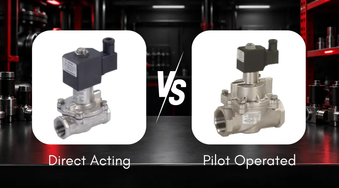
Why This Valve Selection Between Direct Acting & Pilot Operated Solenoid Valve Impacts System Reliability
In industrial automation and fluid control systems, selecting the correct solenoid valve is not a routine procurement activity—it is a performance-critical engineering decision.
The choice between direct acting and pilot operated solenoid valves directly affects:
- System reliability and uptime
- Flow performance and pressure stability
- Energy consumption across the lifecycle
- Maintenance frequency and failure risk
Direct acting solenoid valves use electromagnetic force directly and operate at zero pressure differential. Pilot operated valves use line pressure assistance and are better suited for high-flow applications with sufficient differential pressure.
In real plant conditions—whether in oil & gas facilities in the Middle East, cement plants in Egypt, or process industries in the US—incorrect valve selection for a given application can result in:
- Failure to actuate during startup
- Excessive pressure drops and flow restriction
- Coil overheating and premature failure
- Unplanned shutdowns and safety risks
This guide provides a technical, application-driven comparison to help EPC engineers, OEMs, and plant operators make accurate, specification-based decisions.
Quick Engineering Answers (For Fast Decision-Making): Direct Acting Vs Pilot Operated SOV
- Zero pressure or vacuum system? → Use Direct Acting Valve
- High flow with stable pressure? → Use Pilot Operated Valve
- Fast response required (milliseconds)? → Direct Acting
- Energy efficiency in large systems? → Pilot Operated
- Dirty or contaminated media? → Prefer Direct Acting with Proper Filtration
Understanding the Core Difference
Direct Acting Solenoid Valve
An electrically actuated valve where the solenoid coil directly lifts the plunger, overcoming spring force and fluid pressure—without relying on system pressure.
Pilot Operated Solenoid Valve
A pressure-assisted design where the solenoid controls a pilot orifice, and system pressure is used to actuate the main valve via a diaphragm or piston. It can be conceptualized as two valves working in tandem: a small direct acting solenoid acts as the "brain" controlling the "muscle" of a larger pressure-actuated main valve.
Direct Acting Solenoid Valve: Technical Breakdown
Working Principle
- Coil energization generates a magnetic field proportional to ampere-turns (NI), producing a lifting force on the ferromagnetic plunger
- The plunger lifts directly against spring pre-load and fluid pressure force (F = P × A, where P = fluid pressure, A = orifice area)
- Flow path opens instantly
- De-energizing closes the valve via spring return
Engineering Note: The solenoid magnetic force must always exceed the combined opposing forces: F_solenoid > F_spring + F_fluid_pressure. This is why direct acting valves have limitations of upper limit approx. 20–30 bar for standard designs—beyond which the coil cannot generate sufficient force. If high pressure is required in a direct acting solenoid valve, a specialized design must be used.
Engineering Characteristics
| Parameter | Specification |
|---|---|
| Operating pressure | 0 bar to ~450 bar (design dependent) |
| Minimum pressure requirement | 0 bar (vacuum compatible) |
| Cv (Flow coefficient) | Low (limited by small orifice size, typically DN1–DN10) |
| Response time | Very fast (10–50 ms) (depends on multiple factors) |
| Power consumption | Higher (coil performs full actuation work) |
| Fluid temperature range | -60°C to +180°C (material-dependent) |
| Duty cycle | ED 100% (continuous duty capable) |
| Coil wattage (typical) | 0.35 – 30 W (AC/DC, design-dependent) |
Temperature Note: As ambient and fluid temperatures rise, the solenoid coil's electrical resistance increases per the relationship R = R₀[1 + α(T − T₀)], reducing current and therefore magnetic force. This can reduce the maximum allowable operating pressure at elevated temperatures.
Material & Design Considerations
- Body materials: Aluminum Anodized or Powder Coated, Brass, SS316, SS316L
- Seal materials: NBR (−25°C to +75°C), FKM/Viton (−20°C to +160°C), EPDM (−50°C to +130°C), PTFE (−60°C to +180°C), Fluorosilicon (−60°C to +190°C)
- Coil insulation class: Class F (155°C) for standard applications, Class H (180°C) for high-temperature environments. Rotex has standardized Class H for flexibility purposes as it offers superior temperature handling capability.
- Enclosure protection: IP65 (dust-tight, protected against water jets) / IP67 (dust-tight, protected against temporary immersion up to 1 m) / IP68 (dust-tight and protected against continuous submersion)
- Orifice size: ~1 mm to 10 mm (small orifice design)
Note: Rotex can provide all component material in Stainless Steel to withstand environmental corrosion such as Offshore applications. Rotex offers options in body material, seal material, and various certification options to meet regional requirements on a global basis.
Typical Industrial Usage
- Analyzer panels and sampling systems
- Vacuum systems
- Low-pressure fuel gas lines
- Dosing and precision control systems
- ON/OFF Valve, Emergency Shutdown Valve, Control Valve
- Compressor applications
- Fire Fighting applications
Pilot Operated Solenoid Valve: Technical Breakdown
Working Principle
- Solenoid energizes and opens the small pilot orifice (typically 0.5–2 mm diameter)
- Pressure differential forms across the diaphragm or piston: upstream pressure P1 acts on the lower face while the pilot chamber above is vented to downstream pressure P2
- Net force (P1 − P2) × A_diaphragm lifts the main closure element
- Valve closes when pilot orifice closes, pressure equalizes across the diaphragm, and spring force reseats it
Critical Physics: The minimum differential pressure required is determined by: ΔP_min = F_spring / A_diaphragm. Typical values range from 0.5 to 2.0 bar. Below this threshold, the diaphragm cannot lift, and the valve fails to open.
Engineering Characteristics
| Parameter | Specification |
|---|---|
| Minimum differential pressure | 0.5–2.0 bar (design-dependent) |
| Operating pressure | Up to 700 bar (design dependent) |
| Cv | High (large main orifice, typically DN7–DN100+) |
| Response time | 50–300 ms |
| Power consumption | Lower (solenoid controls pilot only; typically 0.35–10 W, design-dependent) |
| Main closure element | Diaphragm (low-pressure fluids) or Piston (high-pressure hydraulics) |
Design Sensitivities
- Pilot orifice clogging: The pilot orifice (typically 0.5–1 mm) is highly susceptible to particulate contamination; a 40–100 µm strainer upstream is strongly recommended.
- Requires stable upstream pressure above minimum ΔP threshold during full cycle.
- Orientation sensitivity: In some designs, horizontal mounting of the plunger axis can cause gravitational offset on the diaphragm, affecting seating force—always verify with manufacturer datasheets.
Typical Industrial Usage
- Compressed air systems
- Water treatment plants
- Steam lines in process industries
- Chemical processing systems
- Bulk fluid handling
- Pollution Control, Pulse Bag Filter Cleaning
- High Flow High Pressure requirements
Direct Acting vs Pilot Operated: Engineering Comparison
| Parameter | Direct Acting | Pilot Operated |
|---|---|---|
| Actuation force source | Electromagnetic (solenoid only) | Pressure-assisted (fluid differential) |
| Minimum Pressure | 0 bar | 0.5–2.0 bar ΔP required |
| Max orifice size (standard) | Up to DN10 | DN7 to DN100+ |
| Flow Capacity (Cv) | Low | High |
| Response Time | 10–50 ms | 50–300 ms |
| Coil power draw | 0.35–30 W | 0.35–10 W |
| Contamination handling | Less Sensitive (larger relative orifice) | Sensitive (pilot orifice blockage risk) |
| Best application | Precision / low flow / zero pressure | High flow / bulk / stable pressure |
Cv, Flow, and Pressure Drop: Critical Sizing Factors
The flow coefficient Cv quantifies how much flow a valve passes at a given pressure drop and is the primary sizing parameter for solenoid valve selection. Undersizing causes excessive pressure drop; oversizing leads to poor control and unnecessary cost.
Cv = Q × √(SG / ΔP)
- Q = Flow rate (US gal/min or m³/hr)
- SG = Specific gravity of fluid (water = 1.0)
- ΔP = Pressure drop across valve (bar or psi)
Engineering Note: Always calculate Cv from system requirements—never estimate. A valve with insufficient Cv creates a permanent bottleneck in the pipeline. For gases and steam, apply compressibility corrections and use the appropriate gas Cv equation per ISA-75.01.
Failure Scenario: Pilot Operated Valve Below Minimum ΔP
Silent Failure — Solenoid Energized, Valve Remains Closed
- System pressure drops below threshold (~0.5 bar)
- Diaphragm net lifting force drops to zero or negative
- Valve fails to open despite solenoid being energized
- No flow passes — solenoid energized but valve closed (Silent failure)
Key diagnostic challenge: Electrical continuity checks confirm the solenoid is healthy. The failure is purely mechanical/hydraulic—a standard multimeter test will show no fault, making root-cause diagnosis non-trivial without a pressure gauge at the inlet.
Real Industrial Case: Middle East Refinery
In a Middle East refinery, pilot operated valves installed on low-pressure flare lines failed during startup due to insufficient pressure differential. The solenoid coils showed no fault, making diagnosis non-trivial.
Resolution: Replacing them with direct acting valves resolved the issue — highlighting that electrical continuity does not confirm actuation in pilot operated designs.
Types and Configurations
Direct Acting Configurations
- 2/2-way NC/NO — Single flow path, normally closed or normally open. Standard isolation duty.
- 3/2-way valves — Two flow paths, used for actuator control or diverting service.
- Explosion-proof variants — ATEX Zone 1/2, IECEx certified, flameproof (Ex d) or increased safety (Ex e) enclosures for hazardous area installations.
Pilot Operated Configurations
- 2/2 diaphragm valves — Standard water, air, and gas service.
- 2/2 piston valves — High-pressure hydraulic and oil service; rated to 700 bar in specialized designs.
- 3/2 and 5/2 pneumatic control valves — Actuator control in pneumatic circuits; double-acting cylinder service.
- NAMUR-mounted valves — Direct-mounted on rotary/linear actuators per VDI/VDE 3845. Compact, tubing-free installation.
- Internally vs. externally piloted — Internal pilot taps from valve inlet (P1); external pilot uses a separate instrument air supply for corrosive or low-pressure media.
Internal vs. External Pilot: When It Matters
| Feature | Internal Pilot | External Pilot |
|---|---|---|
| Pilot pressure source | Tapped from valve inlet (P1) | Supplied from separate external source |
| Use case | Stable inlet pressure ≥ min ΔP | Unstable, low, or zero inlet pressure |
| System complexity | Lower | Higher (additional tubing/fittings) |
| Typical example | Compressed air headers | Low-pressure gas lines with separate instrument air |
| Media | Non-corrosive media | Can be used with corrosive media |
External pilot is selected when system pressure is insufficient or unstable for internal piloting—for example, during startup sequences or in vacuum-break applications.
Selecting the wrong valve operating principle is one of the leading causes of automation instability. Rotex application engineers help OEMs and EPCs validate differential pressure, flow requirements, media compatibility, and fail-safe logic before specification.
Selection Criteria and Engineering Guidelines: Direct Acting Vs Pilot Operated
1. Pressure Conditions
Zero / fluctuating pressure → Direct Acting
Stable pressure > 0.5 bar → Pilot Operated
High pressure (>30 bar) → Pilot Operated (piston type)
2. Flow Requirement (Cv)
Calculate required Cv using Cv = Q√(SG/ΔP)
Low Cv (< 2.0): Direct Acting sufficient (up to ½" size)
High Cv (> 2.0): Pilot Operated preferred
3. Response Time
Safety-critical / fast cycling (< 50 ms) → Direct Acting
Standard process control (50–300 ms) → Pilot Operated
4. Media Condition
Contaminated / particulate-laden → Direct Acting preferred
Clean, filtered media → Both suitable; add suitable strainer for pilot and direct acting valves
5. Power Availability
Limited power (battery-backed, remote) → Pilot operated (lower wattage)
Unrestricted power → Direct Acting acceptable
6. Compliance & Safety
Hazardous area (Zone 1/2, Div 1/2) → ATEX / IECEx certified valve required
Safety Instrumented Systems → IEC 61508 (component SIL) / IEC 61511 (system SIL) compliance required
SIL-rated valves must have documented PFD and proof-test intervals.
7. Installation Constraints
Orientation-sensitive (pilot diaphragm designs) → Confirm with manufacturer datasheet
Space-constrained panels → Direct Acting (more compact)
NAMUR actuator interface → Pilot Operated (5/2-way standard, 5/2 & 3/2 convertible)
Industry Applications (Global Context)
Oil & Gas
Direct acting: ESD systems, low-pressure gas lines, instrument air panels
Pilot operated: High-flow gas distribution headers, compressor control valves
Cement Industry
Direct acting: Analyzer & ON/OFF Valve, Control Valve, ESD
Pilot operated: Pulse jet dust collectors (high-frequency switching), compressed air systems, kiln cooling air circuits
Steel Plants
Direct acting: Intermittent cooling water systems, quench valves
Pilot operated: Blast furnace combustion air systems (high flow, stable pressure)
Pharma & Clean Systems
Direct acting: Precise dosing, low-volume CIP/SIP circuits
Pilot operated: Utility water/steam systems (USP/WFI-grade with SS316L + PTFE seals)
Water & Wastewater
Pilot operated: Bulk water handling, main distribution mains
Direct acting: Chemical dosing, pH/chlorine injection systems
Failure Modes and Reliability Risks
Direct Acting Valve
Coil Burnout
- Root Cause: Voltage fluctuation, ambient overtemperature, continuous duty on undersized coil
- Prevention: Monitor coil temperature; specify ED 100% rated coils; use surge suppressors
Orifice Clogging
- Root Cause: Particulate in media, scale buildup
- Prevention: Suitable upstream strainer; periodic proof-test
Plunger Sticking
- Root Cause: Magnetic remanence, corrosion
- Prevention: AC coils (self-clearing); stainless plunger
Pilot Operated Valve
Fail to Open at Low ΔP
- Root Cause: Pressure below minimum threshold
- Prevention: Monitor system pressure; select external pilot if needed
Diaphragm Fatigue / Rupture
- Root Cause: High cycling frequency, media incompatibility, over-pressure
- Prevention: Verify material compatibility; specify piston type for >16 bar
Pilot Orifice Blockage
- Root Cause: Contaminated media
- Prevention: Suitable upstream strainer; regular maintenance; external pilot operated valve preferred
Back-Pressure Opening
- Root Cause: Outlet pressure exceeds inlet
- Prevention: Verify P1 > P2 at all operating conditions including shutdowns
Lifecycle Cost and Efficiency Impact
Total Cost of Ownership (TCO) extends beyond purchase price. Energy consumption, maintenance intervals, and failure consequences all determine which valve type delivers better long-term value for a given application.
Direct Acting
- Higher energy consumption — coil wattage 10–30 W continuously; entire actuation load carried by the coil
- Lower initial cost — simpler design, smaller body, fewer internal components
- Better reliability in zero-pressure and low-pressure systems — no minimum ΔP dependency
- Best TCO in precision dosing, analyzer systems, and ESD applications
Pilot Operated
- Lower energy cost — coil wattage 3–10 W; solenoid controls pilot only, not the full flow orifice
- Higher initial investment — diaphragm or piston mechanism, larger body, more complex assembly
- Better performance and lower TCO in high-flow systems
- Best suited for compressed air, bulk water, steam, and high-flow process lines at stable pressure
Selection Cautions
- Using pilot valves in low-pressure or startup-transient systems — valve fails to open silently
- Ignoring Cv sizing — leads to pressure drop, flow restriction, and system underperformance
- Oversizing direct acting valves — unnecessarily large coil, excessive power draw, larger footprint
- Not accounting for contamination — pilot orifice blockage in unfiltered systems
- Incorrect coil selection — mismatched voltage, wrong insulation class, or wrong duty cycle rating
- Ignoring orientation requirements — particularly for diaphragm-type pilot valves mounted horizontally
Summary
The choice between direct acting and pilot operated solenoid valves must be based on a structured engineering evaluation. No single valve type is universally superior—the correct selection depends on the specific combination of process conditions, media characteristics, and application criticality.
Engineering Evaluation Checklist
A complete specification review must address all five parameters before valve type is determined:
- Pressure conditions — including startup transients and minimum ΔP verification
- Flow (Cv) requirements — calculated from system data, not estimated
- Response time — matched to application criticality and cycle frequency
- Media characteristics — cleanliness, viscosity, corrosivity, and temperature range
- Environmental conditions — temperature extremes, hazardous area classification, IP rating
Final Decision Logic
- Direct Acting → Zero/low pressure, precision control, fast response, vacuum, contaminated media
- Pilot Operated → High flow (high Cv), energy efficiency, stable inlet pressure, large orifice
Incorrect selection leads to operational failure, increased maintenance, and energy inefficiency. A structured engineering approach — including Cv calculation, ΔP verification, media compatibility check, and standards compliance review — ensures reliable system performance and long-term operational stability.